

This document Crun provides essential information on Permanent Capacitor Motors and Capacitor Start Capacitor Run Motors. It covers the importance of correct wiring in preventing damage to motor capacitors and windings due to frequent stop/starts or changes in rotation direction. The document emphasizes the need for qualified electricians to reconnect terminations and highlights the usage of three-phase motors with single-phase frequency inverters for optimal performance. Additionally, it includes wiring diagrams for single-phase motors with mechanical centrifugal switches and electronic current circuits. Van Houcke UK Ltd’s contact details are also provided for further assistance. Visit their website for more details.

L1
N
L1
N
Crun
Crun
U1
U2
Z2
U1
U2
Z2
L1
N
L1
N
Cstart
Cstart
U1
U2
Z1
Z2
U1
U2
Z1
Z2
L1
N
L1
N
Crun
Crun
Z1
U1
U2
Z1
Z2
Crun
Crun
L1
N
Crun
U1
U2
Z2
L1
N
Cstart
U1
U2
Z1
Z2
Crun
U1
U2
Z1
Z2
Crun
L1( )N
N( )L1
L1( )N
N( )L1
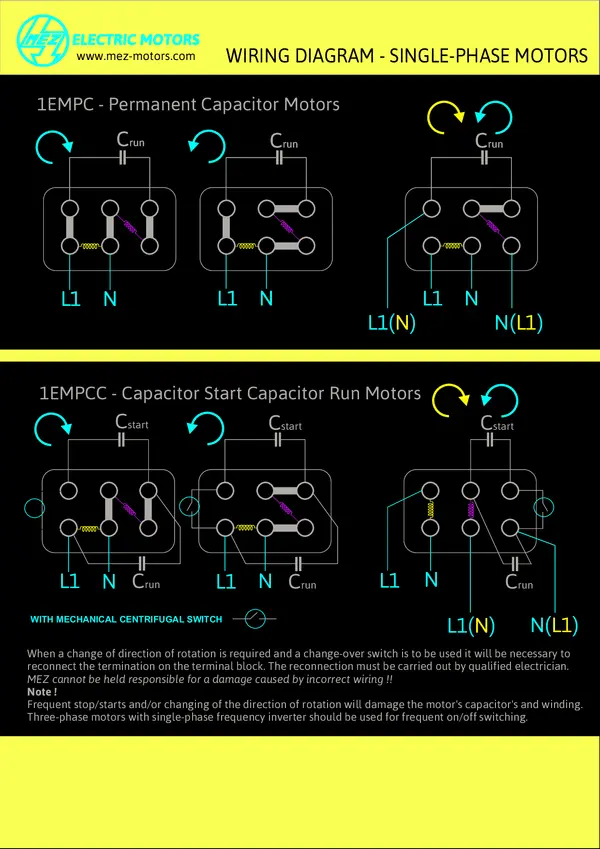
1EMPC - Permanent Capacitor Motors
1EMPCC - Capacitor Start Capacitor Run Motors
When a change of direction of rotation is required and a change-over switch is to be used it will be necessary to
reconnect the termination on the terminal block. The reconnection must be carried out by qualified electrician.
Frequent stop/starts and/or changing of the direction of rotation will damage the motor's capacitor's and winding.
Three-phase motors with single-phase frequency inverter should be used for frequent on/off switching.
MEZ cannot be held responsible for a damage caused by incorrect wiring !!
Note !
WIRING DIAGRAM - SINGLE-PHASE MOTORS
WITH MECHANICAL CENTRIFUGAL SWITCH
www.mez-motors.com
ELECTRIC MOTORS

Cstart
Z1
BLUE
BLUE
RED RED
L1
N
L1
N
Crun
Crun
U1
U2
Z2
U1
U2
Z2
L1
N
L1
N
Cstart
U1
U2
Z1
Z2
U1
U2
Z2
L1
N
L1
N
Crun
Crun
Z1
U1
U2
Z1
Z2
Crun
Crun
L1
N
Crun
U1
U2
Z2
L1
N
Cstart
U1
U2
Z1
Z2
Crun
U1
U2
Z1
Z2
Crun
L1( )N
N( )L1
L1( )N
N( )L1
1EMPC - Permanent Capacitor Motors
1EMPCC - Capacitor Start Capacitor Run Motors
When a change of direction of rotation is required and a change-over switch is to be used it will be necessary to
reconnect the termination on the terminal block. The reconnection must be carried out by qualified electrician.
Frequent stop/starts and/or changing of the direction of rotation will damage the motor's capacitor's and winding.
Three-phase motors with single-phase frequency inverter should be used for frequent on/off switching.
MEZ cannot be held responsible for a damage caused by incorrect wiring !!
Note !
WIRING DIAGRAM - SINGLE-PHASE MOTORS
BLUE
BLUE
RED RED
BLUE
BLUE
RED RED
WITH ELECTRONIC CURRENT CIRCUIT
BLUE
BLUE
RED RED
Van Houcke UK Ltd
www.vanhoucke.co.uk

U1
YELLOW
U2
BLACK
Z2
BLUE
Z1
RED
WINDING LEADS COLOUR CODING
MAIN
START WINDING
WINDING
WIRING DIAGRAM - SINGLE-PHASE MOTORS
Van Houcke UK Ltd
www.vanhoucke.co.uk


