•
more
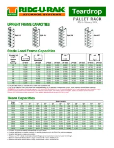
Teardrop Beam Upright Frame Capacities
Uploaded by: nuniuniuh2
Please log in to your account to continue.
Don't have an account? Sign up
Onyx Storm
Iron Flame
Icebreaker Novel by Hannah Grace
Report This Content
Copyright infringement
If you are the copyright owner of this document or someone authorized to act on a copyright owner’s behalf, please use the DMCA form to report infringement.
Report an issue