Isometric Projection Techniques and Applications

Isometric Projection Techniques and Applications

Isometric projection is a crucial technique in technical drawing that allows for the three-dimensional representation of objects on a two-dimensional surface. This unit covers essential principles of isometric drawing, including the correct angles for horizontal edges and the representation of circles as ellipses. It also provides step-by-step instructions for creating isometric views of various geometric shapes, such as cylinders, cones, and prisms. Ideal for students in engineering and design courses, this resource enhances understanding of spatial visualization and drafting skills.

Key Points

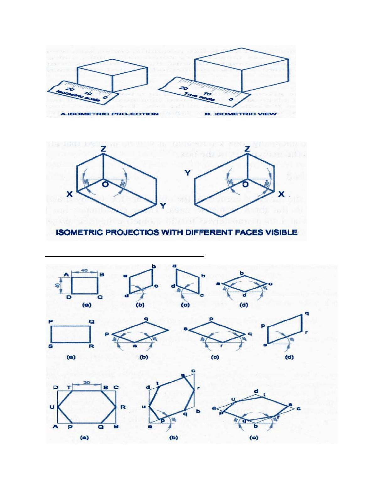
  • Explains the fundamental principles of isometric projection for technical drawing.
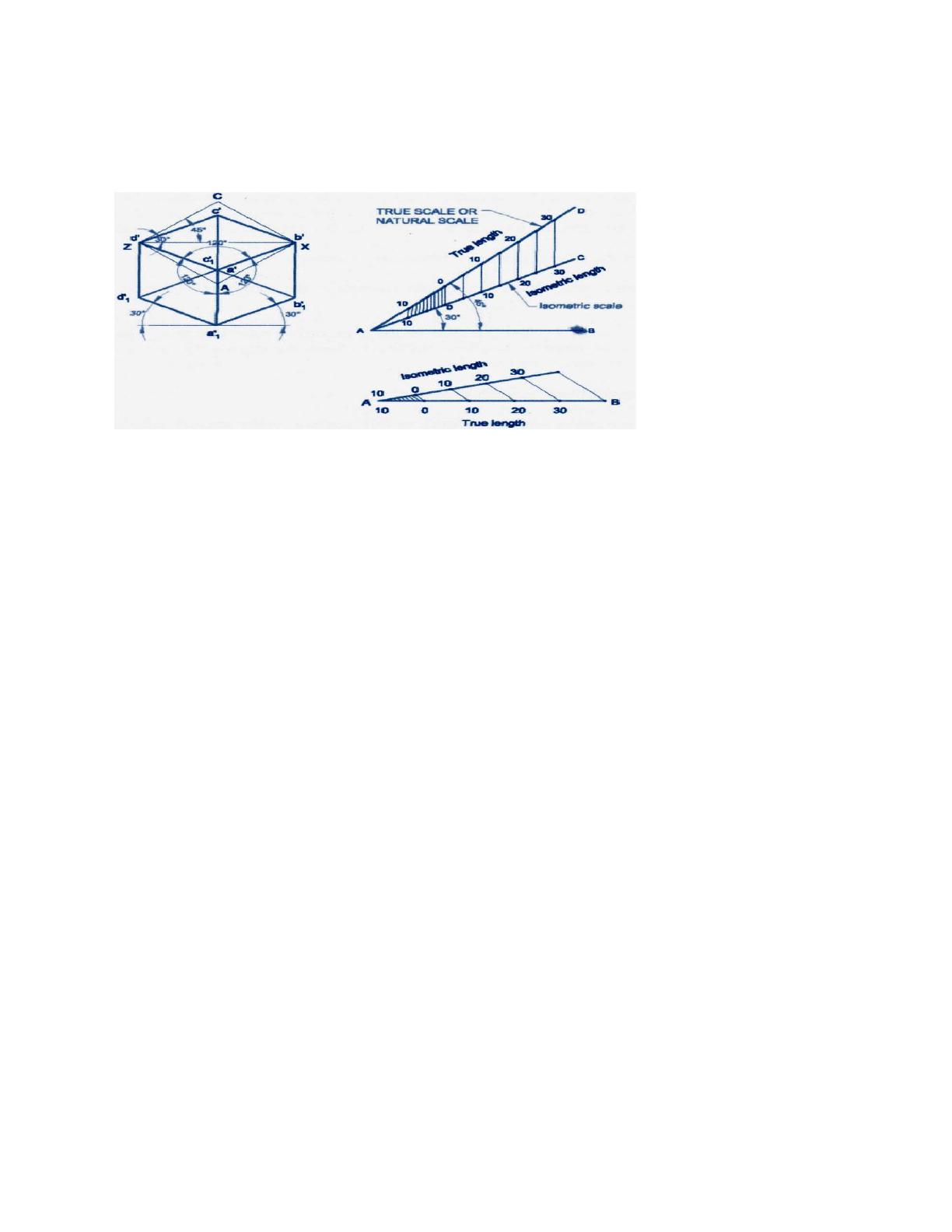
  • Covers the correct angles for horizontal edges and vertical lines in isometric views.
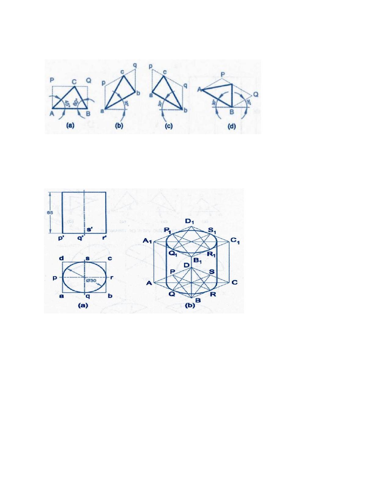
  • Includes detailed instructions for drawing isometric views of cylinders, cones, and prisms.
  • Demonstrates how to represent circles as ellipses in isometric drawings.
120
/ 17
Unit-5
ISOMETRIC PROJECTION
Importance Points in Isometric:
1. For drawing the isometric, the object must be viewed such that either the front -right or the left
edges becomes nearest.
2. All vertical edges of the object remain vertical in isometric
3. The horizontal edges of the object which are parallel to the isometric axes are drawn at 30° to
the horizontal.
4. The inclined edges which are not parallel to the isometric axes should not be drawn at the
given inclination in isometric. These inclined edges are drawn by first locating the end points in
isometric and then joined.
5. All circles are represented as ellipses in isometric.
6. All construction lines have to be retained as thin lines and the visible edges are to be shown as
thick lines.
7. Generally the hidden edges need not be shown in isometric unless otherwise required either
for locating a comer, or an edge, or face, or mentioned.
8. Unless otherwise specifically mentioned to draw the isometric view or isometric drawing all
dimension lines parallel to the isometric unless otherwise if mentioned.
9. No dimensions are indicated in isometric unless otherwise mentioned.
10. The given orthographic views need not be drawn unless required for consideration
Isomertric view for different geometrical surface.
Isometric view of triangle
1) Draw the isometric view of a cylinder of diameter 30 mm and height 65mm.
/ 17
End of Document
120
You May Also Like

FAQs of Isometric Projection Techniques and Applications

What are the key principles of isometric projection?
Isometric projection involves drawing objects in three dimensions on a two-dimensional plane. The key principles include maintaining vertical edges as vertical and drawing horizontal edges at 30 degrees to the horizontal. Additionally, inclined edges not parallel to the isometric axes are determined by locating endpoints in isometric space. This technique helps in visualizing complex shapes and is widely used in engineering and architectural drawings.
How do you draw a cylinder in isometric projection?
To draw a cylinder in isometric projection, start by establishing the height and diameter of the cylinder. The vertical edges are drawn straight up, while the circular base is represented as an ellipse. The ellipse is drawn at a 30-degree angle to the horizontal, ensuring that the proportions reflect the cylinder's dimensions accurately. This method allows for a clear representation of the cylinder's three-dimensional form.
What is the significance of isometric projection in engineering?
Isometric projection is significant in engineering as it provides a clear and accurate way to represent three-dimensional objects. This technique helps engineers and designers visualize how components fit together in a space, facilitating better communication and understanding of design concepts. By using isometric drawings, professionals can convey complex information succinctly, making it easier to identify potential issues before actual construction.
What geometric shapes can be represented in isometric projection?
Various geometric shapes can be represented in isometric projection, including cylinders, cones, prisms, and pyramids. Each shape has specific drawing techniques that ensure accurate representation. For example, while cylinders are drawn with elliptical bases, prisms and pyramids require careful attention to the angles and proportions of their faces. Mastering these techniques is essential for anyone involved in technical drawing or design.
How are circles represented in isometric drawings?
In isometric drawings, circles are represented as ellipses due to the angle of projection. This transformation occurs because the three-dimensional nature of the circle is flattened onto a two-dimensional plane. The ellipse's major and minor axes are drawn at specific angles to maintain the circle's proportions, allowing viewers to perceive the circular shape accurately within the isometric context.

Related of Isometric Projection Techniques and Applications